Sunday, December 15, 2013

Low and High Voltage CAN go in the Same Box

All our lights are low-voltage.  I looked for boxes for the switches, but I was surprised to find the plastic LV boxes were expensive, and in my view, not that great.  I searched for a steel box and found one!  It is the Hubble product pictured below, the price is reasonable, (less than the LV mud-ring boxes) and the divider is removable (additional $1 for the divider), so the box can accommodate both regular household voltage and low voltage in the same double-gang box.  We used double-gang boxes for all our switches and plugs in the house - (almost all).  Most will have a CAT6 cable and an 18g. cable in the LV side, plus whatever goes on in the household current side.  From these, we can eliminate power adapters in the house by providing LV direct from the plug, and we also can use any 12V devices, and have DC lamps (so DC power direct to LED COB lamps).  DC-DC boost or buck pucks are available online now for about $5, so you can get almost any voltage you want by placing it in the box (we are supplying 28V), and it would remain within the electrical code rules as long the voltage remains below class 2 wiring limits.  In addition, every plug location becomes a data/voice/LV/automation/sensing/instrumentation node as well, without adding additional boxes all over the place.  So we can have things like motion sensing that controls things far away from the box, microphones, speakers, bluetooth, wifi, fire sensing, temperature, humidity, etc.
In many of the switch locations, there is no household current component, so the whole 2-gang box is for LV.


There are virtually no octagonal boxes in our project - Just one, actually in the utility room because I wanted to have a different source of lighting while the LV lighting system was being worked on.
You can see the LV wires come from above the plywood - they were incorporated into the acoustic floor assy above.  This could be done with 115V also, but you would likely need for it to be in conduit depending on the acoustic floor thickness.


Exterior Cladding is Finally Going Up

The exterior cladding is finally coming together, but its hard to photograph due to scaffolding, and the difficulty of getting a good camera angle.
We've made so many changes to the project it is no longer funny, so I've figured out now that one way to avoid changes is to build it fast!  Everyone seems very unwilling to change things once the money is spent and the construction complete.  Sadly, that is not our current situation!

Here's a rendering of what we are doing:

I offered to go up there and paint the roof white (because we both felt we chose the wrong colour shingles for it), but she's not keen on the white idea, so the brownish mistake will remain.  I find the house pleasing, though it is simple.

And here's a pic of the cladding going up:

Removable Basement Floors and Interior or Exterior Insulation Placement

A basic decision that one faces early in the design of a super-insulated building is the strategic choice of interior/exterior insulation placement and thermal mass.  This a strategic decision because it has far-reaching implications and ripple effects.  Think of the building as a shell on all sides, including the parts in the ground.  If we are designing an airtight envelope without thermal bridging, then we want to avoid having some of the insulation inside, and some on the outside - it can be done, but this frequently leads to thermal bridges and sealing problems.  For example, if we have insulation under the footings, (this being outside the structure of the shell), but then we want to have insulation inside the basement walls, how to connect the insulation under the footings to the insulation inside the basement?  The problem is there because in general, insulation materials are weak and soft, while structural materials are hard, but conduct heat.  To simplify the design and construction greatly, and improve the effectiveness of the insulation system, work to have all the insulation either outside the shell, or inside the structural shell.  Cross-overs are to be avoided.  In our case, we decided to place all the insulation inside the shell, and forego the thermal mass benefits - I believe thermal mass benefits are less well proven than insulation benefits, and that 'thermal' mass can be achieved without 'mass' (for ex. by the use of water - a very thermally massive material without much mass, that can be moved around).  
SO, here are more photos of our basement floors - they are above all of our interior insulation (about R55, or 15" of Roxul) above our basement concrete slab.  As posted earlier, they are removable, and they are a common material - regular construction lumber 2x12.  which means we can remove and replace pieces, but we can also remove and look underneath.  We're currently pretty happy with these floors, and the system feels very solid to walk on - as if the floors were resting directly on concrete.  It turns out the wood has shrunken a little in the 2 months since we installed it - but only the pieces that were wetter.  those nice planks in the 2nd photo have not shrunken at all.
Some astute observers have commented that the floors will allow moist interior air to go into the spaces below the slabs.  What will happen to this moist air when it reaches the cold concrete some 17" below?  Well, we have Tyvek under the floor boards in one area to prevent this bulk movement of air, but most of the floor is left without any kind of air barrier.  Since it is removable, we can make a correction if this turns out to be an issue, but I have a feeling the issue is fairly minor for a couple of reasons.  If we think of regular basements, many have no insulation under the concrete floors, and they are perhaps a bit damp on muggy, hot summer days, but often this problem is short lived in the Toronto climate.  In our case, there is a floor assembly blocking the bulk movement of air to some degree, and in addition, the space beneath our floors may be warm for much of the summer due to our under-floor (sub-slab) heat storage strategy.  This raises the temperature of the basement concrete slab right when the chances of hot moist air condensing on it may be highest, which should reduce that whole issue quite a bit.


However, as there could be a small concern, we did place some sensors at the bottom of the floor insulation, in three locations.  The photo below shows a small pump with tubing, a water level sensor, and a temp/humidity sensor in the background.  The sensors are inexpensive devices for Arduino, and cost about $5 each.  The pump was from Princess auto and was about $20.  We had some problems with our basement floor pour - there was not enough slope in some areas, and during the big Toronto flood in July 2013, we noticed a little water in three locations on the floor, and so marked these spots and placed these little pumps to transfer the water to the sump pit.
Later on, as the systems become live, we will be able to report the fluctuations in temperature and humidity at the bottom of our basement floor assemblies.
We will also probably place sub-slab soil temperature sensors as well, one day...


Sunday, October 27, 2013

Cellulose vs Urethane Foams - Again

I've noticed that in much older posts I reported on costs of various types of insulations.  More on this here. We have now finalized our cellulose insulation contract with Greensaver - a not-for-profit in the Toronto area.  Costs for dense-packed cellulose insulation for walls seems to break down like this, at least on our project:

Walls:  4085 cubic feet, at 3.5lb/cf density = 14,300 lb cellulose, at 33 lb/bag, we need 433 bags at about $10ea. - so materials for the walls are $4330.

Attic:  4183cf at 2.0 lb/cf = about 8400 lb in the attic, or about $2550 worth of material.

Labour in the walls is about twice the material cost, and labour in the attic, about 70% of material costs.

Much thanks to Climatizer insulation of Toronto for providing a fantastic price on the material for our project!  (They've had a tour of our house and took a step to support us as a contribution toward green initiatives).  Here are the bags we will be using:

http://www.climatizerinsulation.com/CelluloseInsulation/Overview.aspx

In the past I've noted that spray-foams are about 10x the costs of cellulose and the other fibrous insulations. There is a bit more to note regarding this issue, which has some impacts on the 10x difference.  I discovered this video on youtube: http://www.youtube.com/watch?v=F26eIesDDQg&feature=player_detailpage showing the use of pour foam - liquid foams that you pour into things.  This is very similar or the same stuff that is used in the spray foam process, (it is basically the same, but additives may differ).  The video points to Aeromarine Products http://aeromarineproducts.com, where you can purchase the foams right from the website.  You'll notice you can purchase about 500 cubic feet of 2# foam for about $3900 - which works out to $7.80/cf, or about 10.8 cents/sf-R.  This is still a lot more than cellulose, at $0.303/cf, or $0.0072/sf-R.  Something like 15x the cost on the materials.  Here is a place you can purchase spray-foam kits: http://www.sprayfoamkit.com/products/spray-foam-kits, and they also give you the prices right online - I love it when they do this.  Here the price of spray foam on their largest kit works out to $14.3/cf - almost twice the price of the pour-foam.  This is some 30x the cost of cellulose, R for R (not accounting for the fact that cellulose takes about twice the space to achieve the same R levels - the value of space and the construction details required to build this space for cellulose are pretty variable - but then, we are also not accounting for the health and environmental footprints of the two materials, which are vastly different as well, with cellulose miles ahead on both accounts).  Note that labour costs are not included in the comparison, but given the labour portions noted above, we are still well ahead with cellulose.

Why is spray foam so much more expensive than the pour-foam?  Pressure vessels, and possibly additives - but mostly the pressure vessel/ hoses, gun, etc.  So the interesting point here is that if one must use urethane foam as a DIY, consider buying it in the liquid phase - that's what contractors do.  If you don't need to spray it on walls, but can pour it into a cavity, this is really the way to go.  In our case, we could have poured it into our walls - just like we will be 'pouring' the cellulose.

PS - We are purchasing larger amounts of mineral wool for our project as well, and Winroc has also given us excellent pricing on the material - again, to do their part to support 'green' projects.  Our cost for this material worked out to about $0.034/sf-R - about 4.7 x the cost of cellulose, not accounting for installation labour, which would reduce the cost advantage of cellulose, probably bringing it nearly even with the Roxul.

Tuesday, October 8, 2013

Above Floor Acoustic Assemblies, Basement Raised Floors, Porcelain Tile Exteriors

Damnation!  A power outage caused the loss of almost the entire article I was writing for this post.  Here it goes again.
Below are steel plates with screws holding the plywood floors in line with each other.  We had issues with this (plywood not flush with adjacent plywood) due to the exposed beam ceiling below - we used good-one-side fir plywood for the sub-floor, and it does not come in T&G.  With exposure to weather, the plywood warped and bowed.  The plates, with short screws, bring it back in line.  The steel was clear-coated.  Not shown are holes we drilled just after this step to accept low voltage wiring for lights.  In the background you will see the wood frame for a structural wall.  One must be careful when framing a structural wall over an exposed beam ceiling - or any ceiling.  Having the studs directly over joists is important to reduce warping of the plywood - but this is especially so in exposed beam ceilings.  We also beefed up the bottom plates of the walls to support studs which were between joists - see photo.  There is much to learn about open beam ceilings, in terms of construction finesse.  Some concepts are thus:
  1. Reduced height joists:  Joists in the exposed beam area that are not as tall as the regular joists are advantageous.  This is especially achievable if you have steel-beam joists, but heavy barn beams and other thick members would work as well.  The reduced height allows one to add some thickness of structure above the exposed beams - such as diagonal planking, acoustic floors, and sleepers and wiring chases.
  2. Use all galvanized/stainless hardware to prevent stains due to weather exposure.  Avoid making beams out of thinner, doubled members - It is difficult to double them properly due to the desire to avoid exposed fastenings.  Also, protect the assembly from wetness after the floor above is built.
  3. Beware the structural wall above:  Any wall built above exposed beams should have the studs aligned with the beams.  Point loads due to door openings are to be avoided to reduce uneven loading on the exposed beams, which would cause some beams to deflect more than others, or even twist.


On the right, we are laying in an above-floor acoustic treatment.  Above the 3/4" ply subfloor, it consists of 6mm cork, then thick foamed poly sill gaskets under 1x4 sleepers.  Sliced up roxul batts fill the spaces between sleepers.  This allowed us to run our low voltage lighting wiring above the sub-floor as well (covered by Roxul in the photo), so no wiring is visible in the exposed beam ceiling below.  Then we glued and screwed 3/4" T&G ply to the sleepers, again with short screws.  The sleepers hold the ply together, and the ply holds the sleepers in place. Much cheaper than two layers of ply.  Sound ratings unknown for this assembly, but the difference is very noticeable to our ears.  This we are doing all over the 2nd floor except in washrooms and other areas of hydronic radiant flooring.  Total thickness of this assembly not including the first sub-floor is just under 2". All the door openings were framed to accept this added height.


R-54 Insulation in the basement.  That is an R32 Batt under the 2x6 joists in the basement floor, and an R22 roxul batt will fit between joists.  Below these batts is a space made from PT lattice and landscape fabric, held up 2 to 3 inches using small PT blocks stapled to the batts.  This lattice assembly keeps the insulation off the concrete floor beneath, and provides an unimpeded 'surface' drainage path for any water in the basement to flow towards the sump system.  Any water which remains is able to dry through the insulation upwards.  Any water in the insulation can also flow downwards through the porous landscape fabric.  We were able to get the lattice material super cheap - it was culled material - an entire skidful for $50.  The landscape fabric was about $8 for 150sf.  We stapled it to the lattice.

In the next pic you see a 2x12 pine floor screwed to the joists in in the basement.  We buried the screws about 1/8" so we could later sand the floor and get a somewhat finished surface.  The boards will help to regulate moisture below the floor by passive moisture through them, but also by absorbing and releasing moisture.  The main reason for using this kind of floor - low cost (again, we were able to purchase the material for a great deal - 25% discount from regular contractor pricing) at about $1.25/SF.  This single layer of floor will become the finished floor (with sanding), so it means we can easily remove sections of flooring to inspect/service the spaces below in future.  We therefore install without overlaps and plan the layout to allow removal.  The floor feels extremely solid!  Air sealing is not required at this floor - this was determined from previous air-tightness testing on the building, so we know we are already down to Passive House levels of air-tightness.
The last photo shows large porcelain tiles we plan to use in the cladding.  These are 16x32" porcelain tiles.  The clips you see are stainless steel.  More on this later.

Monday, October 7, 2013

Geo-Exchange is a Largely Untapped Resource in Canada

A new study found ground temperatures in Canada have risen significantly in recent years.  Find this article here.

Jay Egg of Egg Geothermal in Florida writes in the Sept 2013 issue of Plumbing Engineer on some interesting approaches to ground coupling which were certainly new ideas to me.  With geo-exchange (or 'groundsource'), we normally think of a flowing liquid in a closed loop of pipe inside the ground.  This can be a regular pipe made of various materials, or it can be a completely sealed 'Heat Pipe' (look up heat pipes if you are not familiar with them http://en.wikipedia.org/wiki/Heat_pipe).  However, there are other approaches of strong merit as well.

One such approach is the open-loop concept, in which one pumps water from the ground, harvests its thermal potential energy, and re-injects this water into the ground.  This system has the significant advantage of reduced tendency for the local soil to drift in temperature, especially in dry periods.

Another approach is the standing column well (SCW).  This I need to read more about.
Perhaps Here:
http://www.amazon.com/Modern-Geothermal-Engineering-Control-Applications/dp/0071792686/ref=sr_1_1?ie=UTF8&qid=1381195543&sr=8-1&keywords=modern+geothermalhttp://www.amazon.com/Modern-Geothermal-Engineering-Control-Applications/dp/0071792686/ref=sr_1_1?ie=UTF8&qid=1381195543&sr=8-1&keywords=modern+geothermal

A strong resource on ground temperatures in Canada:
http://archive.nrc-cnrc.gc.ca/eng/ibp/irc/cbd/building-digest-180.html

LT

Sunday, May 26, 2013

Super Energy Efficient Lighting for Low Energy Buildings

There is a lighting revolution going on right now - just as there is a solar energy revolution and renewable energy revolution, and energy storage revolution!  I don't remember anyone predicting that after the information age began, we would be going through a major shift in energy and infrastructure.  And this is not to mention Passive House.  I feel like saying people building standard houses today will face some significant obsolescence issues within a few short years - namely in energy, IT, and lighting.  At first these seem like parts of the house one can easily change - but the energy aspect is a big one, and certain things are really hard to justify changing - like missing out on good solar exposure, major thermal bridges, and insulation values that don't cut it.

About the lighting:  Cree announced in December they have an LED that offers 200 lumens per watt (!).
Here's the press release:
http://www.cree.com/news-and-events/cree-news/press-releases/2012/december/mkr-intro

If you are in the big box hardware stores, take a look at the LED offerings.  They are all hovering around 60 lumens per watt right now, if you get a good one.  Most are at 50 lumens per watt, often less.

How to get highly efficient lighting without spending too much?  Low Voltage distribution.
Watch the Video on What Is Lumencache:  http://www.youtube.com/watch?v=7eULjpkf7oE

It seems the thing to do is to separate the COB (chip on board - which is the actual LED chip) from the power supply.  This has two advantages:  purchase a single, centralized, high-efficiency, high-efficacy power supply; and then reduce the cost of the actual luminaires.  All those backward-compatible LED bulbs you can buy to replace the bulbs in your existing fixtures have the significant issue in their design that they have to have an on-board power supply, which is cheaply made to reduce costs and therefore, not that efficient. This also means the cost of those low performance power supplies is included in every bulb.  Eliminate this circuitry and you can improve the lighting.

So, we wire the house as per the Lumencache strategy, but there is another issue to handle.  LED's are pretty sensitive to voltages and current.  Say we have a living room with 12 LED luminaires, each one with nothing more than the COB in the luminaire.  We need to arrange these luminaires into groups that match the voltage and current output of the central LED driver system, or at least keep the demand within the range of output levels available at the central power source.


Welded Stainless Steel Floor - Waterproof

There are a few options for waterproof exterior decks/balconies.
  1. Use roofing on the deck - for small areas, a single EPDM membrane - black or white - over a wood frame.  I would think something needs to go on top of this to protect the membrane and make it more suitable to deck furniture and foot traffic - don't know what.  Regular built-up roofing is not my preference - I've been on this kind of balcony before and found the odour quite strong - so I assume the tar and rubber are off-gassing - anyway, it makes the space unpleasant.  I also would not do this over a deck which has had rigid insulation applied under the roofing membrane.  There is a mushy feeling underfoot, and a sense of doubt as to whether one can place furniture on the surface.
  2. Extruded aluminum deck:  These are generally powder coated extruded aluminum with either a rough or a smooth finish, such as available from Wahoo decks.  These work well, I think, but they are pricey at about $19/SF.  In our case, I couldn't find anyone local who imported them.
  3. Rubber membrane installed in a slanted scallop shape under the deck - it drains to one side - not an elegant solution, though cheap and simple.  Perhaps more suited to decks over soil, to carry water away from the house.
  4. The option we chose:  welded metal.
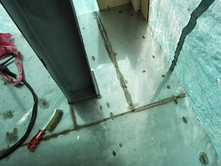
Welded stainless flashings not yet installed.
Why?  Cost of stainless is low right now - about $1.75/lb.  (it was about $4.55/lb ten years ago).  If you calculate the volume we are buying (1/8" thick plate is 18 cubic inches per sf), and multiply by the density of 0.3lb/cubic inch, you get the weight per sf.  Multiplying by price, we get about $9.45/SF - not too costly for smaller areas and it's an easy purchase from local sources.  I figured on a small area, I wanted to try this, and the thermal expansion issues would be minor - I expect this could be an issue on large expanses outdoors - the stainless steel has been in place a month or more now, and it is obvious that despite the high reflectivity, it does get quite warm in the hot sun - like a roof, so thermal expansion is something to keep in mind, as they do on steel roofs.  Stainless steel will also accept tons of abuse without any maintenance, feels solid underfoot, doesn't smell bad, and modifications can be made by welding to it....

I always wondered why people don't employ this solution in their projects for roofs and balcony floors, but even for interior floors.  What I found was that it was a fair bit of work, but not ridiculous, and the result is (I'm hoping) going to prove very practical and durable.  The steel frame in grey primer you see in the photos is regular structural steel, 3" deep C-channels welded to 6" deep hollow beams.  It is far stronger than it needs to be, but we ended up doubling up the joists from what is in the photos - It is a slightly difficult calculation to figure out the floor deflection as a diaphragm, and my rough numbers turned out to be close enough, but I didn't trust them, figuring the floor was supported on all sides.  The deflection of the diaphragm proved noticeable enough and it was simple to add additional joists so they ended up at 9" on centre, originally about 18" OC.  The floor feels very rigid now.  Originally, I thought I would have it plug welded from above and ground smooth, but the mag drill wouldn't stick well enough to the steel through the 1/8" stainless, so we mig-welded from below.  We tig-welded the seams from above (with some mig tacking from below) as the photos show - this is the reason for the tarp.

One thing I really like about stainless - I always feel it is easy to add to it with welding.  You needn't grind off the paint as you would have to with steel, and then re-paint after welding.  I knew I'd want to add some fittings, possibly cleats, hold-downs, etc.  This is easily done on exposed stainless.  The flashings were all welded on.  Most are 22ga, bent on site with a heavy brake - this proved tricky to weld to the 1/8" plate.  The flashing under the door was 14ga, fitted into a grove in the PVC door frame - it is just a window placed on the floor.

Distortion:  There was some distortion.  We had a 1/4"/ft (1 in 50) slope on the floor.  In some areas there was enough distortion to upset this slope and cause pooling - mainly on the long seam you can see near the 6" deep beam, where small sections were welded on.  I'm not too concerned, but we'll be working to correct this and see where it goes.

We used 304L for all the stainless - I'd done a little stainless tig-welding before, and I was familiar with the significant movement of carbon and chromium within the material in the heat-affected zone.  This causes non-stainless areas to appear near the weld afterwards - this is why you need to passivate the stainless after welding (dip into an acid bath to remove the surface areas of non-stainless material).  In our case we would not be giving acid baths to the stainless.  The 'L' in the material designation stands for 'Low carbon', which reduced post-weld corrosion quite a lot.  As it turned out, we did have some surface corrosion appearing on our project, but it was not due to the welds, which seemed to work well.  It was actually due to the use of wire-brushing with steel brushes.  We switched to stainless brushing after noticing this and all was well.

Welding was with both 308 and 309 rod - yes, welding regular steel to stainless is entirely fine and routinely done.

The reflection off the stainless is very bright - it is blinding, actually.  I was hoping this would be a good thing to raise the light incident on the deeply inset glass balcony door - but we did plan to have real wood-slat tiles or boards to block this reflection anyways.  I also plan to do some solar experiments on this balcony, so the reflective surface may be an interesting feature for this.  I've not seen anything on how to integrate this effect into the Passive House thermal modelling.  There are solar reflectors you can purchase that actually track the sun, and reflect it into a given window on the house, such as these:
http://www.creativemachines.com/special_projects/Solar_Mirror/Solar_Mirror.html
http://www.egis-rotor.de/helio_us.html  This would be a significant energetic effect on the house - one that might be an attractive solution in some cases.  This one is really cute:  http://wikoda.com/.
However, if this were part of a design, I would place the reflection-receiving windows high on the wall of the house reduce glare inside the building.

The experience with this has had me consider other metal flooring solutions:  A carbon steel sub-floor/finished floor in the basement (the beauty of this is that the subfloor is the finished floor, reducing labour and materials, and the floor plates - I'd use 4'x2' plates, screwed down - can be removed to gain access to the space beneath)......and also radiant stainless steel staircases (designed well, a radiant staircase can be good for both cooling and heating, since the stair is both a floor and a ceiling).


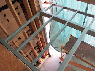
C3x5 (75mm deep, 7.5kg/m) C-channels welded to 3"x6" deep hollow steel tube beam - Beam wall was 3/16" or 1/4" thick.


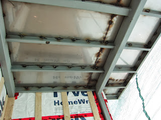
Too bad we've not cleaned off the dark residues from the welding for the photo.  Need more photos of this part of the project.

Wednesday, May 15, 2013

Is Solar Thermal Too Expensive?

Recently we were invited to visit with Patrick Spearing and Suni Ball at Enerworks in Woodstock.  These guys do nothing but solar thermal.  We were pretty much blown away by their knowledge, professionalism, and by how much they taught us about solar thermal in one afternoon.  I'd like to recount some of the knowledge transfer as a way of note taking.

Narva Solar Thermal evacuated tubes and heat pipes


Solar Thermal Collectors:
Enerworks uses Narva glass tubes for their evacuated tubes.  Narva is long established as a UV-light glass tube manufacturer in Germany.  Making high quality tubes for evacuated solar thermal was a natural extension for them, and they've done some interesting things to address two critical issues:  Vacuum and stagnation.  Apparently you will find it very difficult to find any warranties on the vacuums of evacuated tubes.  This is because the borosilicate glass usually used is actually more permeable to helium than regular soda-lime glass.  Why use borosilicate glass, then?  I think it is because the clarity of the glass may be better than regular glass, and perhaps this is cheaper than manufacturing the low-iron soda-lime glass that Narva uses. Anyway, Narva tubes are evacuated to 10 to the -6 torr, (pretty deep vacuum), and the vacuum is guaranteed for 10 years, so this is a big deal.  The vacuum greatly improves the efficiency of the collector, and it also protects the materials inside the heat pipe from freezing.  In addition, the Narva tubes are single-wall, which makes them very robust.  The double-wall tubes are highly susceptible to breaking due to the long moment-arm that multiplies the stresses on the part of the tube that supports the whole inner glass wall.

The other thing is stagnation.  Somebody actually did a bunch of research and analysis and designed a heat pipe which self-limits at ____ temperature.  We asked how this was achieved, and the answer was thus:  by controlling all the physical factors affecting heat pipe design, one can actually make a heat pipe that self-limits its heat transfer and therefore its temperature.  These heat pipes are carefully manufactured to control:
  1. internal volume
  2. chemistry of working fluid
  3. volume/mass of working fluid
Without tight control of these parameters, there can easily be run-away temperatures and significant system stresses which can cause vapour-block, glycol break-down, etc.  It appears the Narva heat pipes contain a lot less working fluid than other heat pipes.  This one fact is sensible to me - it means they can completely vaporize their working fluid, which can limit the heat-pipe's upper temperatures, as well as reduce damage due to any freezing.  It also seems to me that heat-pipe technology is one area in which lower-cost and copycat products may be hard pressed to perform in.

Another Issue:  SRCC ratings for solar panels are somewhat skewed or inaccurate for solar evacuated tube panels.  They count the whole area of the panel without subtracting the spaces between the tubes.  Apparently the Solar KeyMark metric is much better to go by.

Will continue this another day as there is much more to tell.

Saturday, April 27, 2013

6 Emerging Solar Technologies

As I've mentioned before, there is this major energy and renewables revolution taking place right now, and it is moving so fast.  I've read literally hundreds of articles on solar energy innovations poised to lower the cost and increase the output of collectors, all the way back from nanotechnology solar paints - an innovation that seems to have started at the University of Toronto maybe 8, 9 years ago.  Sadly, I've not really been cataloguing these but I'm going to make a start on this now.  Here are just this morning's findings:
The Mother Nature News website is really interesting:
http://www.mnn.com/green-tech/research-innovations/blogs/5-breakthroughs-that-will-make-solar-power-cheaper-than-coal

And a Sixth one is here; Rectennas, or Nantennas - Definitely appears to be one of the more important leaps forward:
http://today.uconn.edu/blog/2013/02/uconn-professors-patented-technique-key-to-new-solar-power-technology/

I've been working on other peoples projects again recently and one of them involves solar thermal technology, mainly because solar thermal can collect up to 80% of the solar energy that strikes it, as opposed to solar PV, which, though cheaper, still takes a lot of area at 15 to 21% efficiencies.
But for all those installing solar thermal on their roofs on projects happening right now, I recommend you also install a conduit or wiring for future PV panels to replace the thermal panels.  Of course, I also recommend the roof structure be given some thought - don't just install the weakest cheapest roof to carry the snow and rain loads - make your roofs face the sun, and make them strong enough to carry solar panels, including hybrid panels, and energy storage panels!


Saturday, April 13, 2013

We are in an Energy Revolution!


Watch this video http://www.youtube.com/watch?v=pZYIZpg2LKo.  It surprised even me - a person already enrolled in the revolution we are witnessing.  It expresses the coming changes in a way that tells everyone this is NOW, and this is huge.  Think of this:  Sunpower was a $10 million company in 2004, now it is worth over a billion dollars.


Recently I've been working with a number of other clients in developing model designs for various buildings, and I keep encountering the doubts that people have about high performance construction, especially regarding finding the sweet spot in terms of optimizing their project and the resulting costs.

I often find myself telling them that what they may not realize is that Passive House is just the beginning, and the 'sweet spot' has already, for the most part, been realized by the Passive House research which has shown again and again that the thing to do is to build to this standard.  This is just the beginning because net zero is next, and then net positive, and complete self-sufficiency.  Only three years ago, net zero was a highly expensive and ambitious endeavour.  Today, numerous governments are talking, even announcing, that their building codes will mandate net zero in a few short years (!).  We are in the midst of a pretty wild and disruptive energy and renewable energy revolution!

It turns out Passive House is, for the sake of simplicity, the proper tool for the creation and design of building envelopes that are the right foundation for this coming energy revolution.  So, all those out there who are feeling timid to go all the way and build to the Passive House Standard, I say, just  go all the way!  You won't regret it.

Look at this host of technologies:

Sunpower announces the X21 series of PV solar panels.  These are 21% efficient, - compare this to the standard PV panel efficiency of 15% - this is some 40% increase from before.....These are available NOW, but sadly, not in Canada.  Look here:  http://us.sunpowercorp.com/homes/products-services/solar-panels/x-series/

Check out this new wind generator - no turbine, no blades, no moving parts!
This same technology applied in reverse is being investigated for aircraft propulsion.

We are completely awash in technological innovations right now.

Sunday, March 3, 2013

Point of Use Water Heating

Imagine going to the kitchen sink and dialing in the water temperature you want.  Then open the single tap and voila - water at the temperature you want, at any volume.  When you close the tap and re-open it, the water is at the same temperature.  Again and again.  No having to adjust to the right temperature every time you open the tap.  Wouldn't that be luxurious?  The technology to do this was available decades ago, but we keep doing things the old way...

Achieving this is simple.  One need only provide a single water line to the faucet.  In that line is a point of use (electric) water heater with a remote control.  The remote control is mounted near the faucet (EcoSmart makes this kind of unit).  The heater is somewhere nearby, but out of sight.  The only issue with implementing this is that the efficiency of water heating is always just 100%. However, one advantage is that there is no hot water anywhere in the system - just at the last two feet of water tubing before the faucet.  No standby losses, although these days they are small in better tanks.

Consider the shower.  Imagine again, only one water line supplying the shower, with an inline point of use water heater with remote.  In the shower, we dial in on the digital display the water temperature we want.  Shower water comes out of the spout at precisely that temperature.  The warm water leaves the shower via the drain, but here, we have a heat recovery device which is some 80% effective.  We give most of the waste heat to the incoming cold water stream just before it contacts the POU heater.  Then the heater finds it very easy to raise the water temperature just the last say 10 degrees Celsius.  In this way, we minimize the heat that leaves the house and the energy and power needed to heat shower water.  If we want a bath, things are quite a different story, and I haven't really thought about what I'll do in that case.

The drain water heat recovery devices out there right now are only some 50 to 60 percent efficient.  Even that is saving half our energy to heat the water, so yay, but for some untold reason, none of these devices take advantage of heat pipes, which I plan to experiment with.

Thursday, February 28, 2013

Energy Efficient Lighting for Passive Houses

Been looking long and hard at energy efficient and sensible topologies for wiring a house or a building.
Here are the needs:
  1. Other than power outlets, we need very little energy for everything else - so why wire them with the 14ga Romex?  I'd like to see a new style of wiring for this stuff.  One that more closely reflects the realities of today - very small loads, and more demand for flexibility.
  2. Long term flexibility:  It is really nuts that we wire the whole house and then hide everything behind drywall - it makes it so hard to make adjustments and changes.  Why can't we have a wiring and control scheme that is modular, flexible, and not expensive?
  3. Every CFL or LED light works on voltages not related to household voltages of 120 or 240V.  All these silly LED lights we buy that fit into regular 115V sockets come with power supplies built-in.  While the bulbs can last 50,000 hrs, the power supplies die after 2000 or whatever.  Why not have a central LED light control/power supply to distribute low voltage to our lights and a host of other things like USB charging jacks, clocks, etc.
  4. We need some low voltage lights for our exposed beam ceiling.  Ever notice the exposed beam ceilings in magazines?  Most of them don't seem to have effective solutions for their lighting.  That's because there is no joist space for them to hide pot lights or wiring or electrical boxes.  A lot of times you see the light is run using a metal conduit (EMT) along the joist, and then to chandelier.  These days I always look for this when I see exposed beam ceilings in magazines.  This can be a vexing problem.  Our solution is to use low voltage (hence few electrical code issues).  The wire is small, and we hope to bury it above the plywood subfloor - this should be easy because we are looking at adding acoustic layers to the subfloor top side anyway (another vexing issue).  Then each wire will enter a surface mounted, hopefully very small light fixture  - something like an under-the-cabinet light.  The trick is finding lights like this that are small, beautiful, and give off tons of light on very little power.
Well, it looks like Lumencache is a product that addresses most of these needs, if not all.  Other than the duplex power outlets, everything is wired with CAT5 ethernet cable.  All devices are wired with home-runs to a central box.  This means every light and every switch, and every other point wired with CAT5 is a potential data node.  It also means the house's wiring is highly flexible and adaptable to future changes - 3-way wiring is done in the central cabinet, rather than in the walls.  A switch can control any light, and this can be changed, and it can control any number of lights, or it can control something other than lights. A light fixture can be changed to be (theoretically for now - not sure if any product yet exists) a smoke alarm, or it can be both, or perhaps a motion sensor with light, or a WiFi Hotspot....

The possibilities are endless.  That is why I am wiring the house with CAT5 instead of Romex.
We will be having CAT5 at every window opening, every door, every light fixture, every switch, and every thermostat, HVAC component, sensor, etc.  In addition, every data point and telephone point - the data and lighting use the same wire, after all.  Sometimes 2.  This makes it all so simple, and I would say very future friendly.

The only thing which I might wire with different cable is the in-wall speakers.  Ethernet connected speakers might be OK, but from what I hear, not quite that good as yet, so we'll probably wire them with 18gauge or something like that.

There are other developments in the home automation field which are exciting.  OpenHAB is an open-source software framework for home and building automation.  Just appeared on the internet last year.  I hope everyone who makes automation gear pays attention to that standard....
These days, the way to go seems to be to control the house with a small PC, powered by an atom processor.  These are inexpensive and consume very little energy - something like the EEEBox 1033.  On this you can run a home automation software like Mcontrol V3.  Only $170 or so online.  Apparently very open and has drivers for hundreds of different protocols so can connect to and talk to virtually everything from your smartphone.

Thursday, February 21, 2013

Link to the Passive House news on Global TV

Here is the link to the Passive House video that was aired tonight on Global news: 

We didn't appear much in the piece, but there were lots of footage of our house, which is most of the construction in this video.  The workers are our crew members, doing actual work two weeks ago.  They used a lot of the information supplied by us, but Lyndon only said one sentence 'on air'.  The filming was supposed to be included in an episode about innovative things happening in construction across Canada, but it is presented in this news piece instead. Hopefully, this will lead to more people knowing about the possibility of passive houses in Canada!

Sunday, February 17, 2013

Our Passive House on TV

Global TV recently approached us for an interview for their upcoming 'The National" news show.  The episode will air this Thursday, Feb 21, 6:30pm on Global TV (channel 3 in Toronto).  They were interested in what Passive House was, and they took some footage of our project, showing the spaces, the double walls, etc.  I hope we don't look too silly!

Friday, January 25, 2013


Thought I would post some of the older  photos.

Lovely attic space will be a sea of cellulose soon.


Solar panel installation.


A view between the double wall frames.

Stainless Steel Exterior Post Anchors

Look around and you will see many exterior columns on residential buildings suffering from corrosion at their bases.  At least I do.  A major reason for this is because pressure treated lumber is frequently used for exterior columns, and the preservative is not compatible with the steel column bases and screws you can get from the lumber store.

One of my beefs with exterior columns is how there is no easy and accessible solution to mount them properly at their bases.  Most of the column bases seem inadequate to me, and in addition they are cheap looking.  Often they are set with their bottom plates in contact with the concrete - an invitation for crevice corrosion.  I looked and looked for solutions, but found them hard to come by.  Finally, I decided to go with steel columns set off the concrete with stainless threaded rod anchors (5/8").  Here are some pics:

Columns offset from concrete SOG about 45mm
5/8" (15mm) stainless steel threaded rod anchors.

That is a temporary door in pic.  Just showing the steel columns and how they're not in contact with the concrete.  Stainless anchors and nuts.

Steel Balcony Frame:  Designed beyond code minimum so as to be strong enough to support a crowd overlooking whatever is happening below.  The frame is completely isolated from the interior of the building which avoids what would be very significant thermal bridging.  this is easy to do when the building is made with a double wall system.  Note the offset joist/outrigger at the far left:  the little 4" x 4" void is to accommodate a concealed downspout.

The floor will be made from 1/8" thick stainless plate welded to the steel.  Probably have wood slats on top of the smooth stainless.

Snow Melt for a Passive House and Recent Photos

Well, we finally poured our slabs on grade and front steps - in Nov. and Dec.  We decided to place snow melt heating loops in the slabs, and it does seem a bit extravagant, but if we actually use it, it means no application of salt to melt ice, and clean, safe entries to the building, especially for the front steps.  As we plan to eliminate the gas service, there will not be any strong heat source to service these snow melt areas -unless we use a wood boiler!

So the idea is to simply run the wood boiler at times when we are expecting significant snow and we need to clear ice from the front steps.  In working out the heat inputs and hydronic flow rates for glycol, etc, I realized a big lesson for exterior snow melt applications.  Normally, radiant slabs are assumed to benefit from high thermal mass - that is when they are indoors, one wants a constant temperature, and heavy massive slabs help to regulate and temper any significant fluctuations such as high solar loads, etc.  Thus, the hydronic heating pipes are frequently installed submerged in slabs of concrete or gypcrete, etc.  However, snow melt works in reverse, in a sense.  In a snow melt application, one wants LOW thermal mass to avoid heating up a big, massive concrete slab just to melt off a thin layer of snow or ice.  Doing the calculations, one finds that it is actually easy to spend more energy bringing the slab to temperature than melting the snow or ice, even when the slab is insulated underneath.  Wish I knew this before I did mine, but for all you guys and gals out there thinking of snow melt, consider this.  Unfortunately, I don't know of any practical solutions to this whole issue at this time, though I have some ideas - we must keep the slab as thin as possible, insulate well underneath, and insulate the edges as well, if practical.  The idea I have been toying with is using a stainless steel or steel plate as the top surface of the slab - or even building the top of the 'slab with a series of rectangular stainless steel tubes and run the heating fluid through these.  This would place the fluid in nearly direct contact with the snow/ice, and diminish heat transfer to the concrete.  The plate would need to have a traction surface, which is an issue because I don't like diamond plate (there is a company 'Algrip' making beautifully dimpled surfaces via laser deposition of metal - no idea of price).  And stainless steel is very cheap right now - just about twice the price of steel.  But it does seem extravagant....

On another note, snow melt components are priced into the thin air of the mountains.  Companies such as Uponor and Viega make the snow sensors, and they are absolutely ridiculous - I cannot understand why.  An ABS plastic housing that holds the sensor (needed during rough-in/casting of the slab) which should cost maybe $20 (perhaps for lack of volume in production), instead commands some $150 in the plumbing/mechanical supply store.  See pic;

This little kit of parts is $150 (contractor price).  The black plastic disc/cover is discarded when the snow melt sensor is installed.  The tube-like thing is made of steel and the temperature sensor is to go into that tube, which sits inside the slab.  The sensor itself is about $1000 contractor price (retail is $1700).
The sensor is just a couple of plates of brass separated by a space.  The resistance between these plates is reduced in the presence of snow and this change triggers a signal which becomes the snow melt system's demand for heat.  Very simple, but the darn sensor is about $1000.  I say it's worth $50 at most.  Since we are no longer at the beginning of the project and money is getting more expensive, we opted to make our own plastic housing and later, when the house is finished and there is more time, we will make our own snow sensor, if needed.  After all, a manual system is not much of an issue - in any case, it is often desirable to heat the slab well before snow appears.
Look closely and you'll see we placed some pipe insulation around the pex tubing where it enters the building.  This is to cushion the tubing in case the slab moves relative to the building.  We also agonized over where to enter the building.  In the end we opted to drill through the wall inside the slab volume, but we drilled the hole with a significant slope so any water from rain or snow will find it harder to flow into the building through those holes.
Add caption
Here is our rough-in:
DIY Rough-in for snow melt sensor made from common plumbing parts - 4" clean-out - we would have to make an adaptor plate to adapt the actual sensor to this bolt pattern, or make our own sensor, which is more likely.

Below are some photos of our snow-melt piping installation.  BTW, I mentioned this to a contractor and he told me they never install 1/2" pex for snow melt - they use 5/8" minimum.  I double-checked my calculations and feel very comfortable with the 1/2" pex - but we'll see if it performs when the time comes.  He is probably thinking of larger areas like driveways.  In our case, it is only on three little concrete slabs.